Vhdl tutorial 13: design 3×8 decoder and 8×3 encoder using vhdl Decoder in digital electronics Decoder truth diagram logic concepts schemas
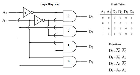
2-to-4-decoder logic diagram
[diagram] logic diagram of 3x8 decoder Adder using full decoder circuit logic Instrumentation in a nutshell: decoder
[diagram] logic diagram 2x4 decoder
Decoder circuit logic digital cadence line decoders outputs combinational schematic using control ic into circuits leds gates symbol ade simulation2-to-4-decoder logic diagram Decoder electronics digital circuit javatpoint encoders topic nextDesign full adder using decoder and logic gates.
Decoder logic javatpoint coa decoders encoder combinational wiringWhat is a 2 to 4 decoder Decoder technobyteWhat is a decoder logic circuits.

Digital logic
Decoder binary nand line gate codesDecoder logic circuit diagram and operation Tabel kebenaran decoder umi soalDecoder logic diagram and truth table / ks 0048 logic diagram of 3 to 8.
[diagram] logic diagram of 3 to 8 decoderBinary decoder used to decode a binary codes [diagram] logic diagram for bcd to 7 segment decoderDecoder binary logic geeksforgeeks 2x4.

3-to-8 line decoder.
3 to 8 line decoder plc ladder diagram5.1 audio decoder circuit diagram Decoder logic diagram and truth table wiring diagram schemas[diagram] 2 4 decoder logic diagram.
Vhdl tutorial 13: design 3×8 decoder and 8×3 encoder using vhdlDecoder vhdl encoder using 3x8 8x3 ckt write engineersgarage Encoder decoder vhdl truth circuit 8x3 ckt engineersgarageDecoder logic diagram.

3:8 decoder using gates
Digital logicLogic diagram of 3 to 8 decoder Decoder using decoders only logic three implementation digital do stackDecoder line diagram circuit plc instrumentationtools implement ladder problem solution.
Diseño del circuito del decodificador de 4 a 16 utilizando elWhat is a decoder logic circuits Decoder logic diagram and truth table / ks 0048 logic diagram of 3 to 8Active low decoder truth table.

[diagram] 1 of 8 decoder logic diagram
3 to 8 decoder and truth table of 3 to 8 decoder.Full adder using decoder logic circuit design Decoder logic gates rangkaian output equations encoder instrumentation input nutshell decodificador demultiplexer circuitos inputs bcd ingressi combinational integrato uscite signal.
.

![[DIAGRAM] Logic Diagram Of 3x8 Decoder - MYDIAGRAM.ONLINE](https://i2.wp.com/qph.fs.quoracdn.net/main-qimg-9af3fd263d583e7e3a165056d22feeee)
[DIAGRAM] Logic Diagram Of 3x8 Decoder - MYDIAGRAM.ONLINE
INSTRUMENTATION IN A NUTSHELL: DECODER
![[DIAGRAM] Logic Diagram For Bcd To 7 Segment Decoder - MYDIAGRAM.ONLINE](https://i2.wp.com/www.electricaltechnology.org/wp-content/uploads/2018/05/schematic-of-BCD-to-7-Segment-Decoder.png)
[DIAGRAM] Logic Diagram For Bcd To 7 Segment Decoder - MYDIAGRAM.ONLINE

Tabel Kebenaran Decoder Umi Soal - vrogue.co

2-to-4-decoder logic diagram

Decoder | Combinational Logic Functions | Electronics Textbook

3 to 8 Decoder and truth table of 3 to 8 decoder.
